*).
Which tabs you see — and which fields and dropdown values they contain — depends on the country resolved from the address on Step 2 and the calculation type you pick on Step 5. See Methodology & Compliance for the per-country rules.
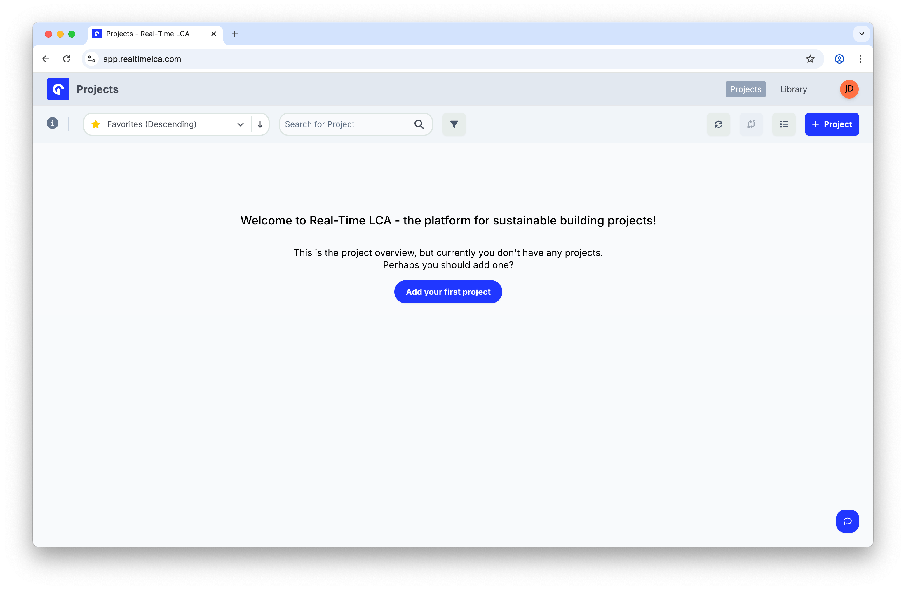
Step 1: Start a new project
From the Projects overview, open the wizard:- If you have no projects yet, click Add your first project.
- Otherwise, click the + Project button in the top-right corner.
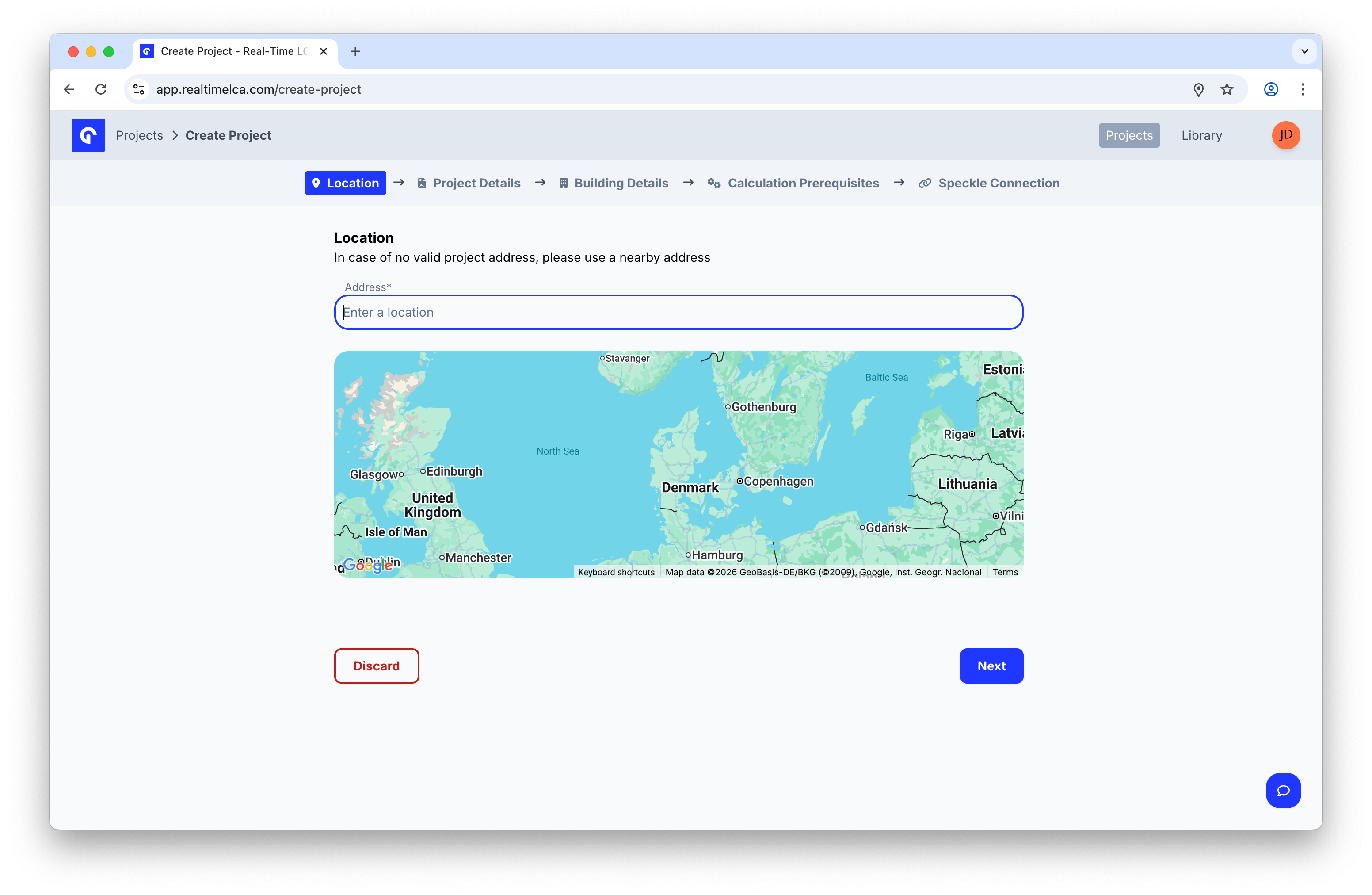
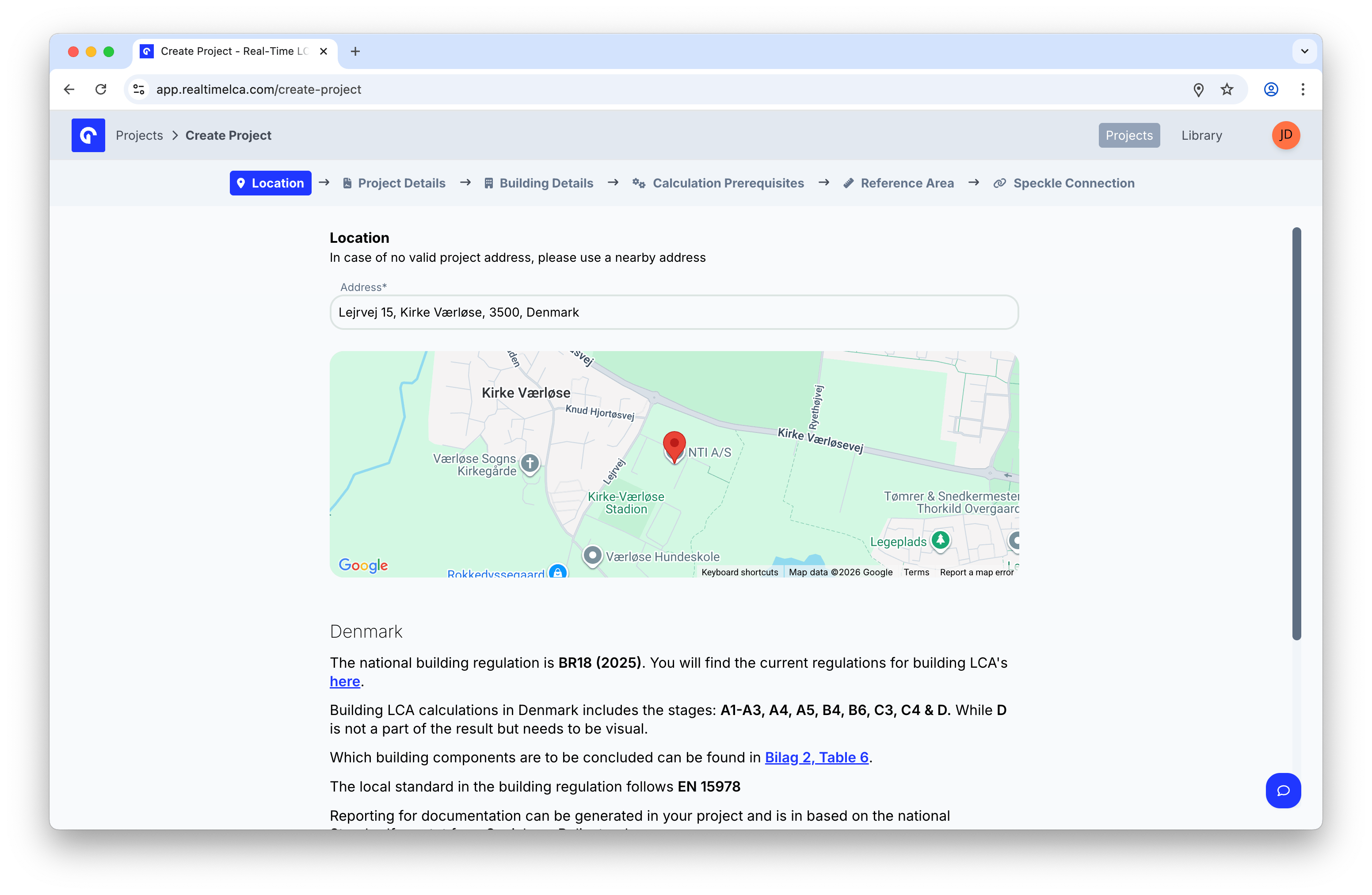
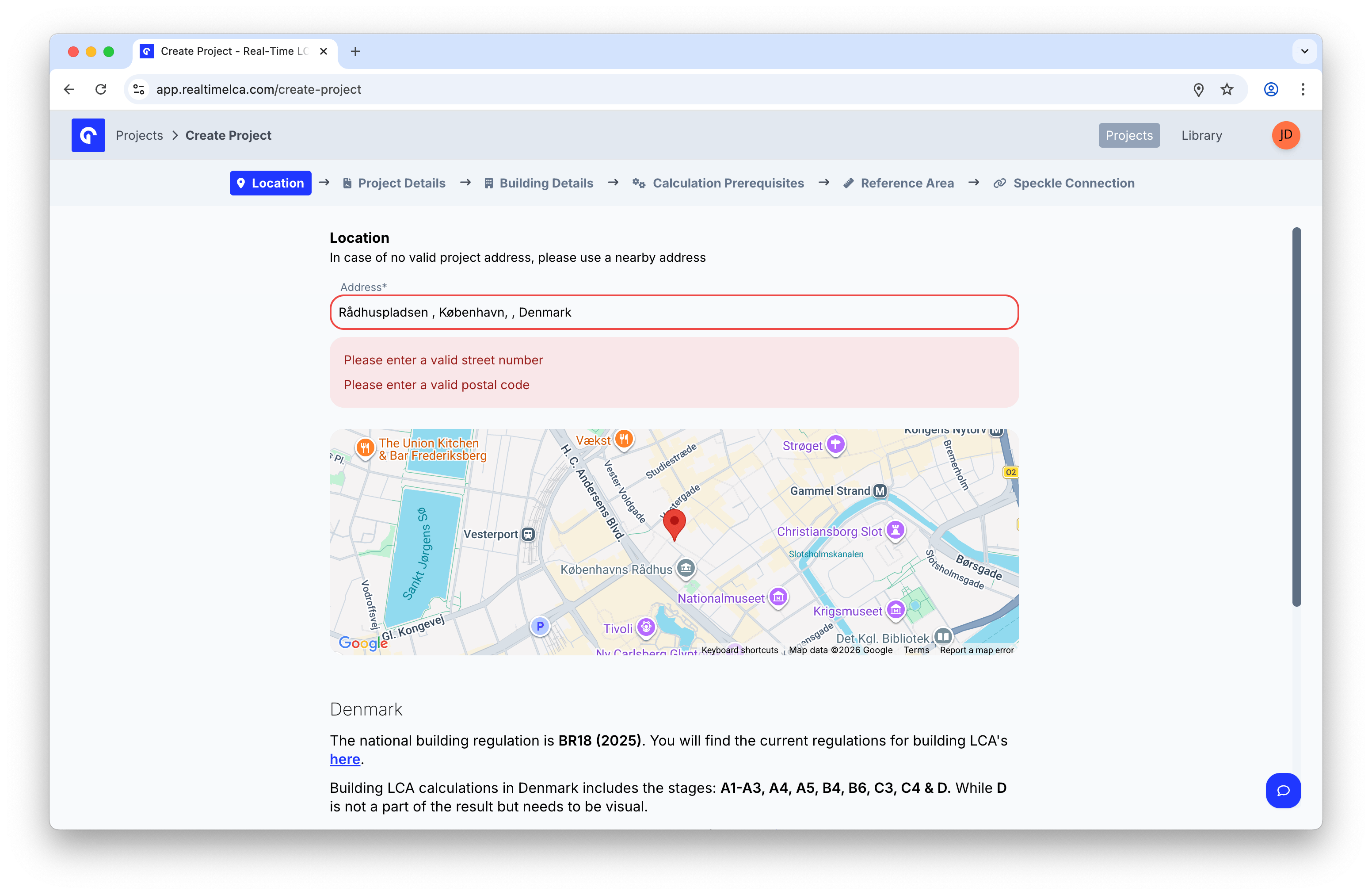
Step 2: Set the location
The location determines which national building regulation, stages, and standards apply to your project.- Start typing the project address in Address.
- Pick a result from the autocomplete suggestions.
- Confirm that the pin on the map matches the building’s location.
Step 3: Fill in project details
Project details identify the project for collaborators and reports.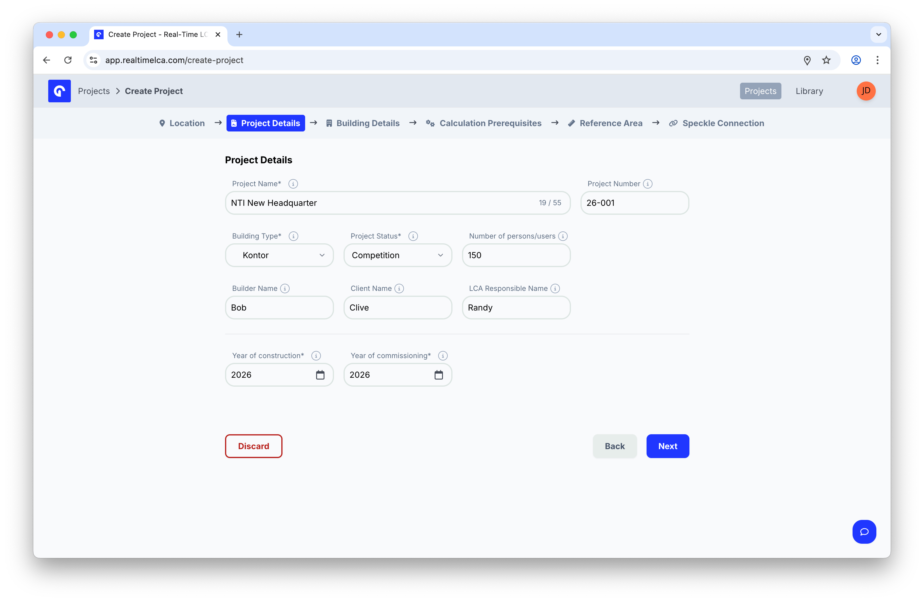
| Field | Description |
|---|---|
| Project Name (required) | A short, recognizable name. Up to 55 characters. |
| Project Number | Your internal project or job number. |
| Building Type (required) | The primary use of the building (for example, Kontor). |
| Project Status (required) | Where the project sits in your workflow (for example, Competition). |
| Number of persons/users | Expected occupancy — used by some calculation types. |
| Builder Name | Name of the builder or contractor. |
| Client Name | The client commissioning the project. |
| LCA Responsible Name | The person responsible for the LCA work in your team. |
| Year of construction (required) | The year construction is expected to complete. |
| Year of commissioning (required) | The year the building is put into use. |
Step 4: Enter building details
The building details capture the heated areas that feed into operational emissions (B6).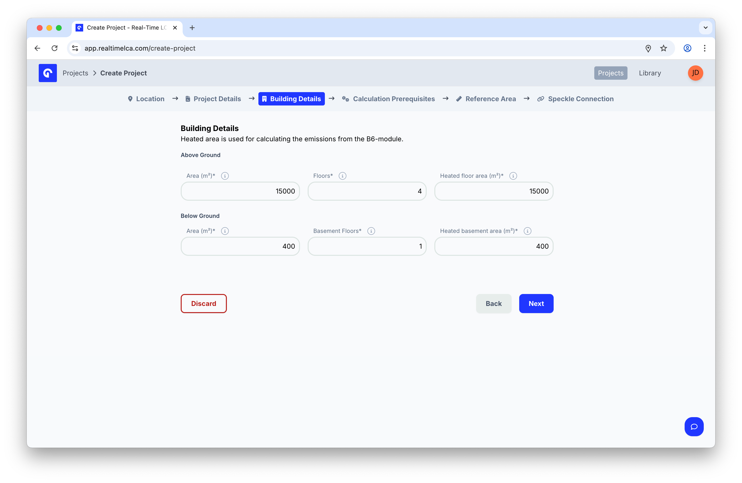
- Area (m²) — Footprint area on that level.
- Floors / Basement Floors — Number of stories.
- Heated floor area (m²) / Heated basement area (m²) — The portion of the area that is heated. Used for B6 (operational energy) calculations.
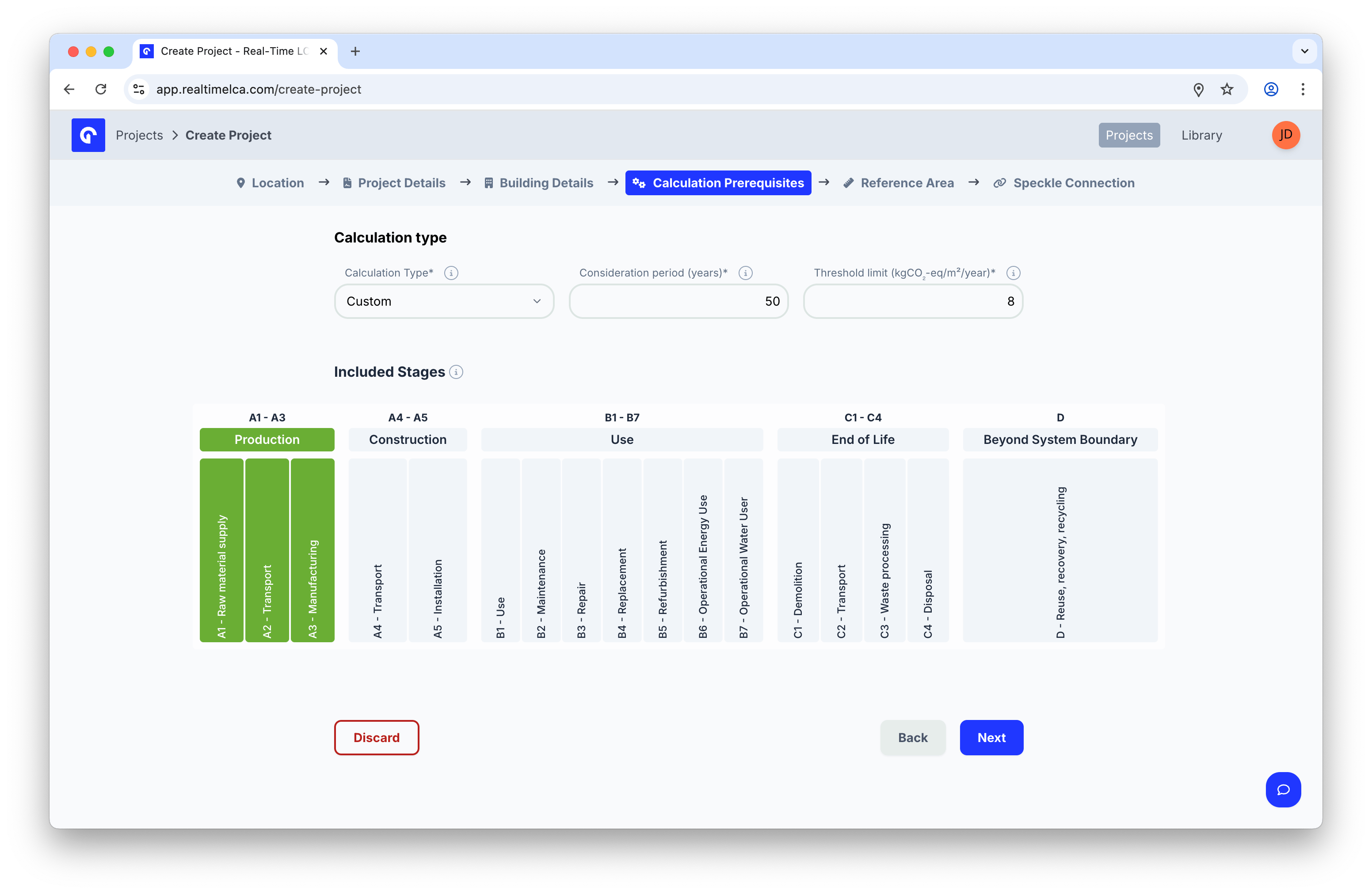
Step 5: Set the calculation prerequisites
Choose the regulation or methodology that your calculation should follow. The Calculation Type controls which life-cycle stages are included, the consideration period, and the CO₂ threshold limit.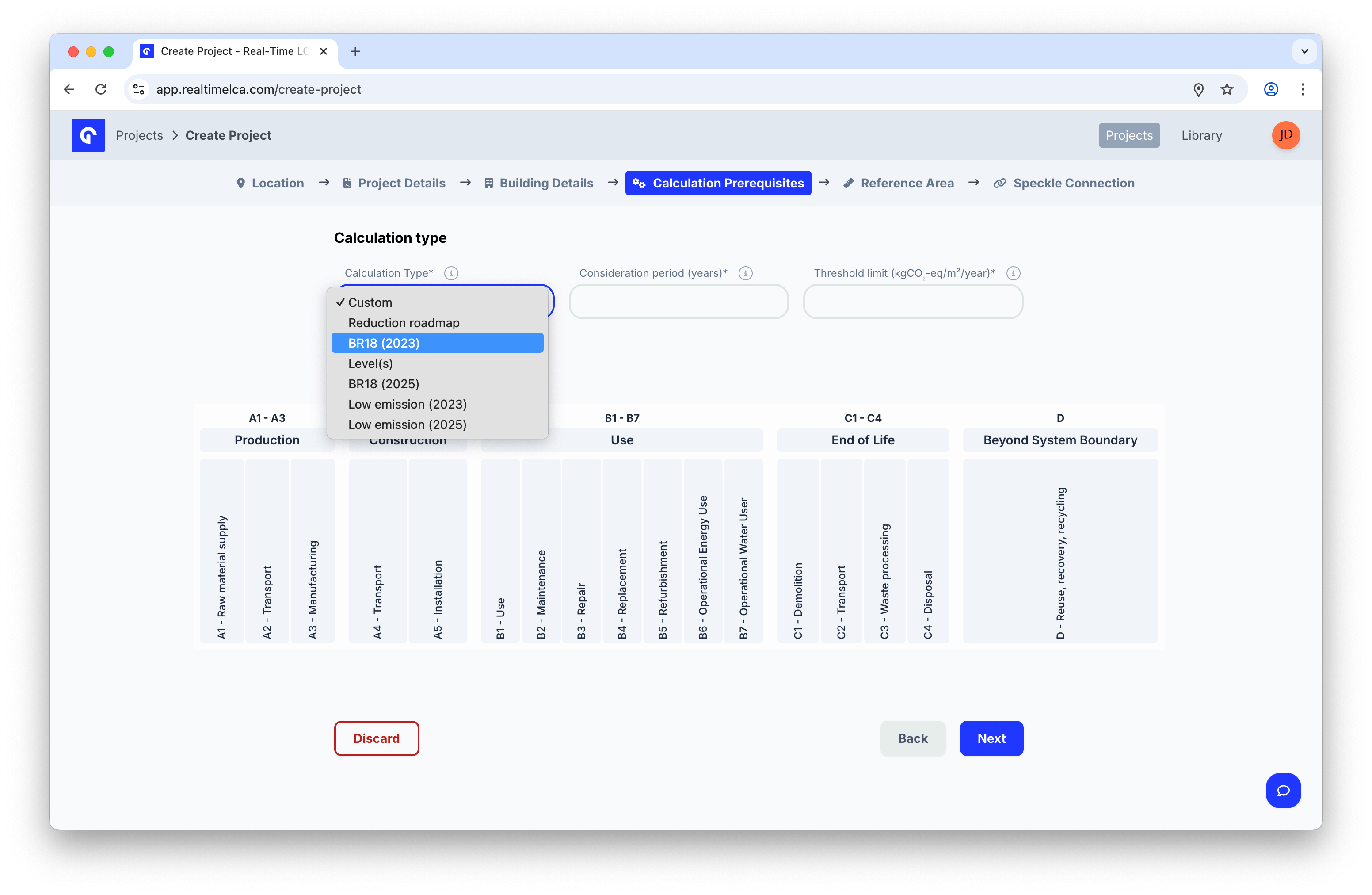
For the full list of calculation types per country — and the rules each one applies — see Methodology & Compliance and the National compliance table. The EU Level(s) framework is available in every country.
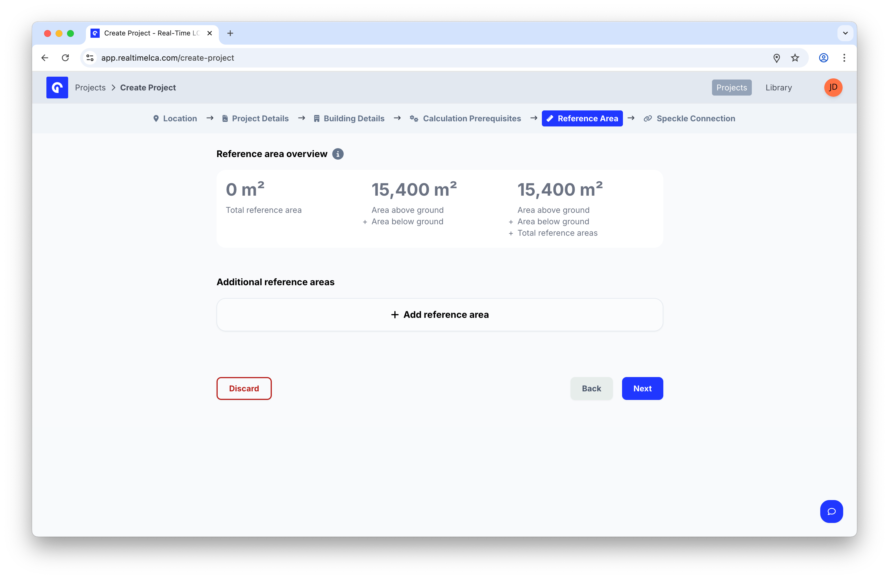
Step 6: Confirm the reference area
The reference area is what the threshold is measured against. Real-Time LCA prefills it from the heated areas you entered in Building Details.Whether the tab is shown, and which conditions are allowed, depends on the country resolved from Step 2. The screenshot below shows the Danish Building Regulations example. See Methodology & Compliance for the per-country rules.
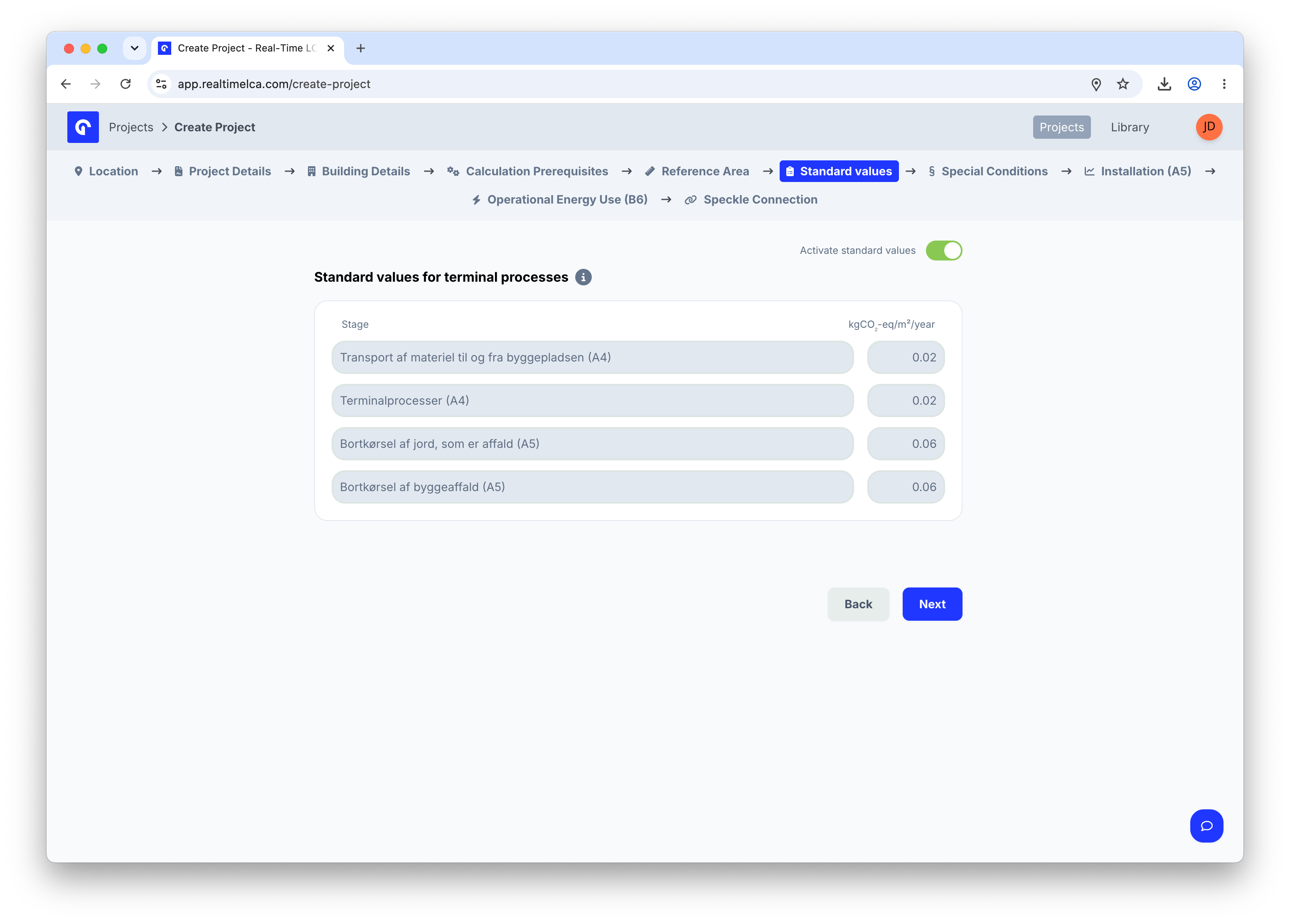
Step 7: Activate standard values
The Standard Values tab is where the wizard pre-populates the terminal-process emission factors that the selected regulation expects — typically the construction-site logistics and waste-removal stages (A4 and A5). The values are read-only defaults from the regulation; flip Activate standard values on to apply them to the project.The factors, stages, and units shown on this tab come from the country’s regulation. See Methodology & Compliance for the rules behind each value. If the selected country has no standard values, this tab is skipped.
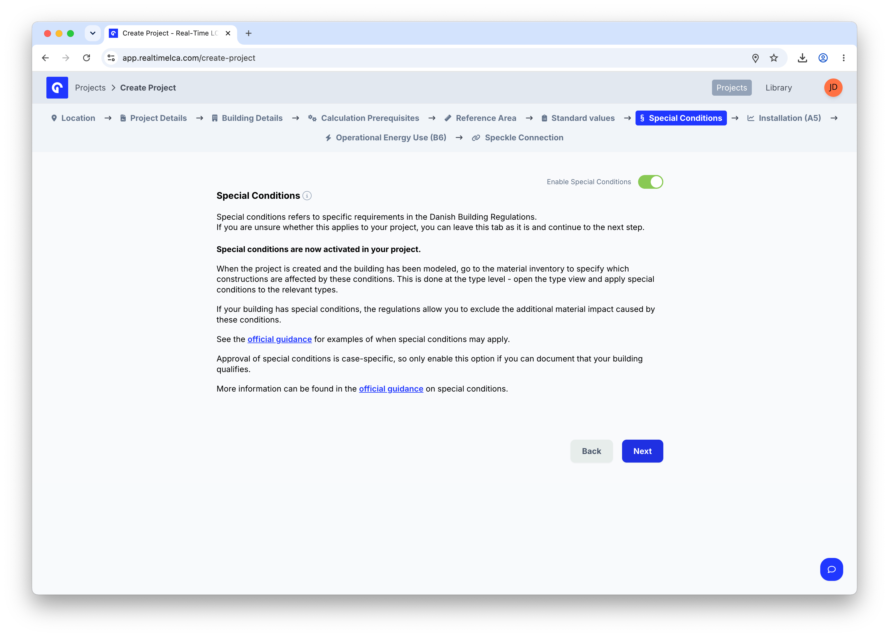
Step 8: Set special conditions
Special Conditions lets the project exclude the additional material impact caused by site-specific constraints — for example, ground or foundation conditions called out in the national regulation. Approval is usually case-specific, so only enable this if you can document that your building qualifies.Whether the tab is shown, and which conditions are allowed, depends on the country resolved from Step 2. The screenshot below shows the Danish Building Regulations example. See Methodology & Compliance for the per-country rules.
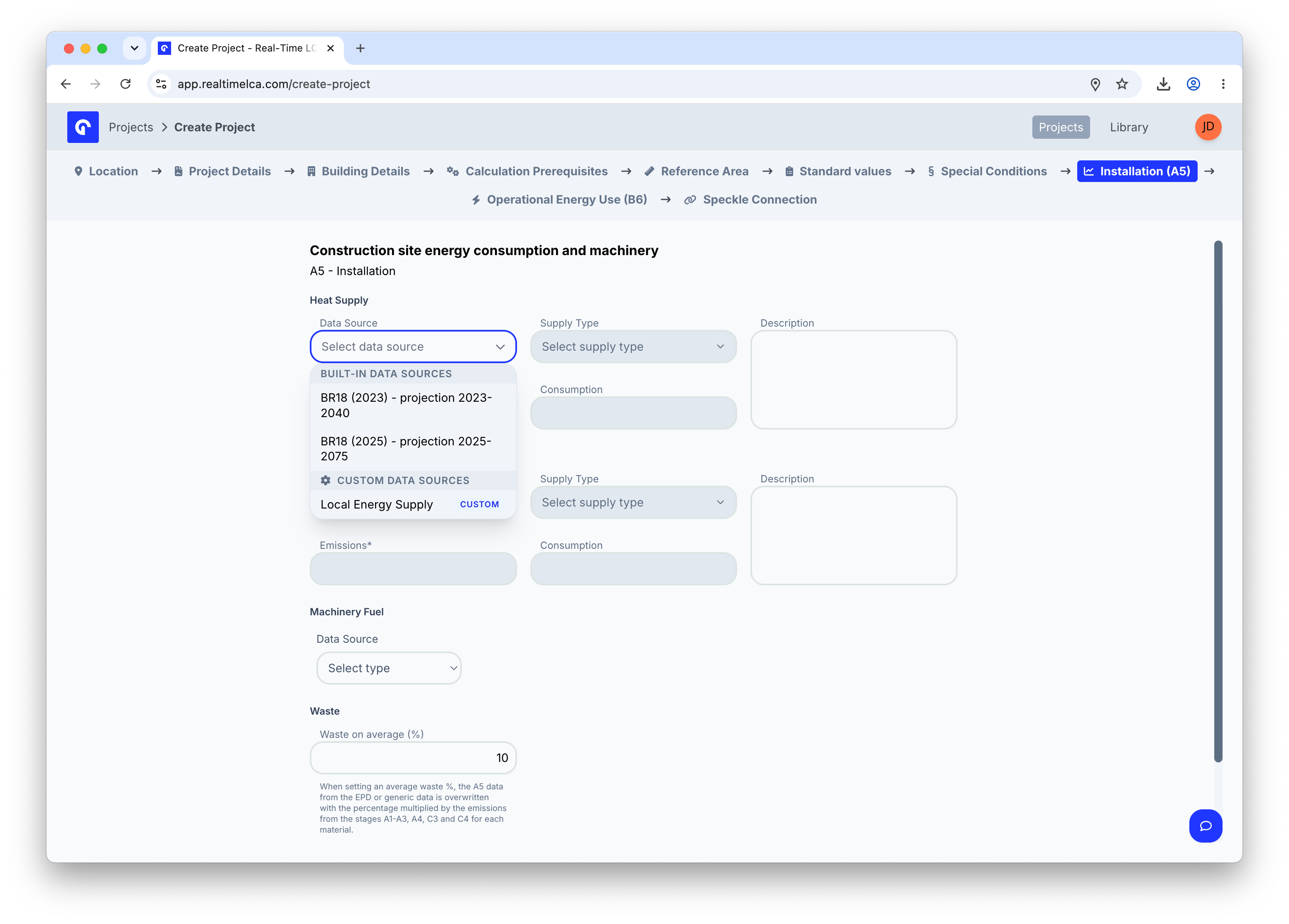
Step 9: Enter A5 installation data
The Installation (A5) tab captures the energy and waste generated on the construction site itself — heat supply, electricity supply, machinery fuel, and the average waste percentage.The data sources available in each dropdown, the supply types you can pick, and whether all three sub-blocks (heat, electricity, machinery) are required depend on the selected country and calculation type. See Methodology & Compliance for the rules behind A5.
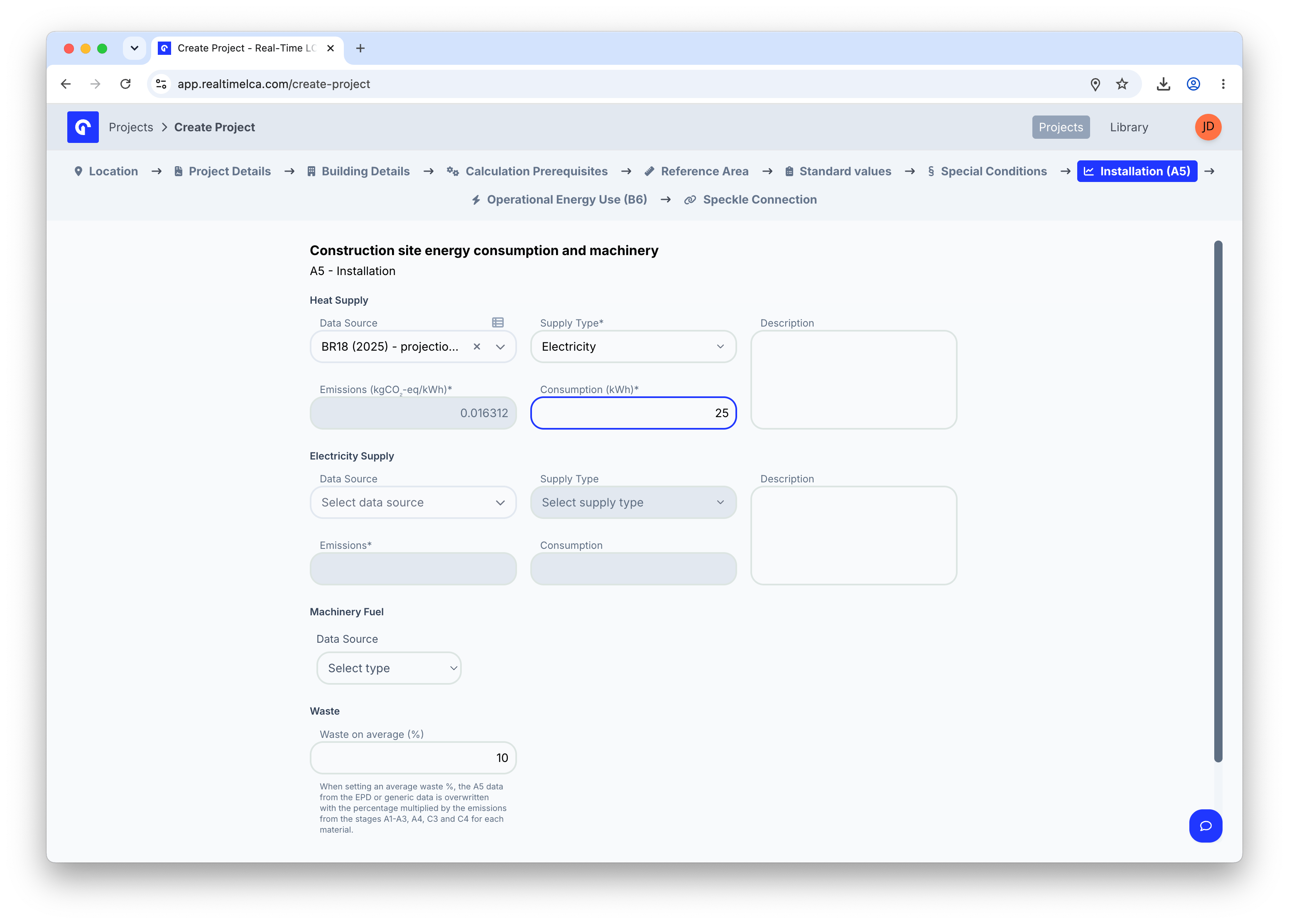
Heat supply
Pick a Data Source to load the emission factor, then choose the matching Supply Type (for example, District Heating, Electricity, or Line Gas) and enter the expected Consumption (kWh). The Emissions (kgCO₂-eq/kWh) field auto-fills from the data source.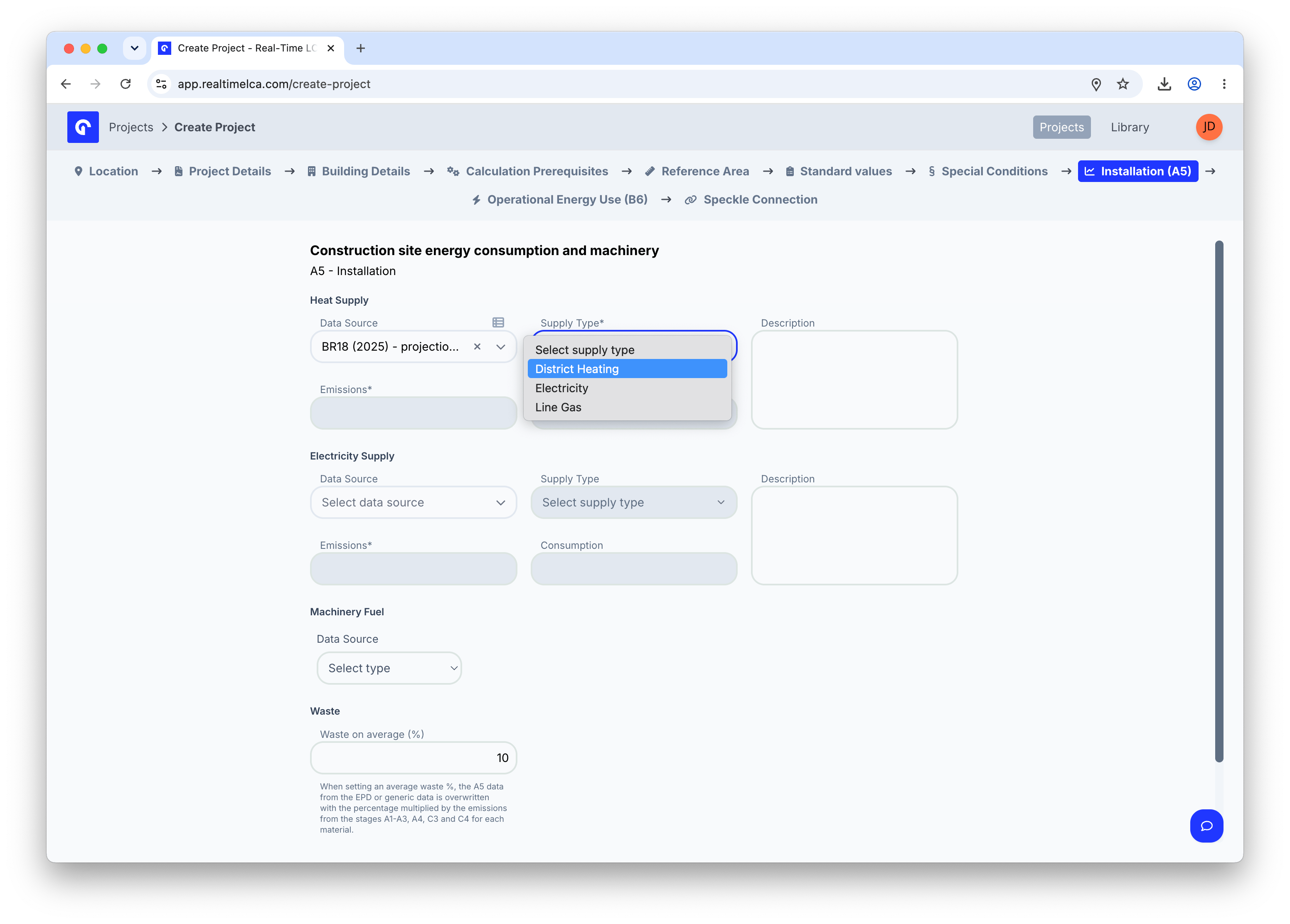
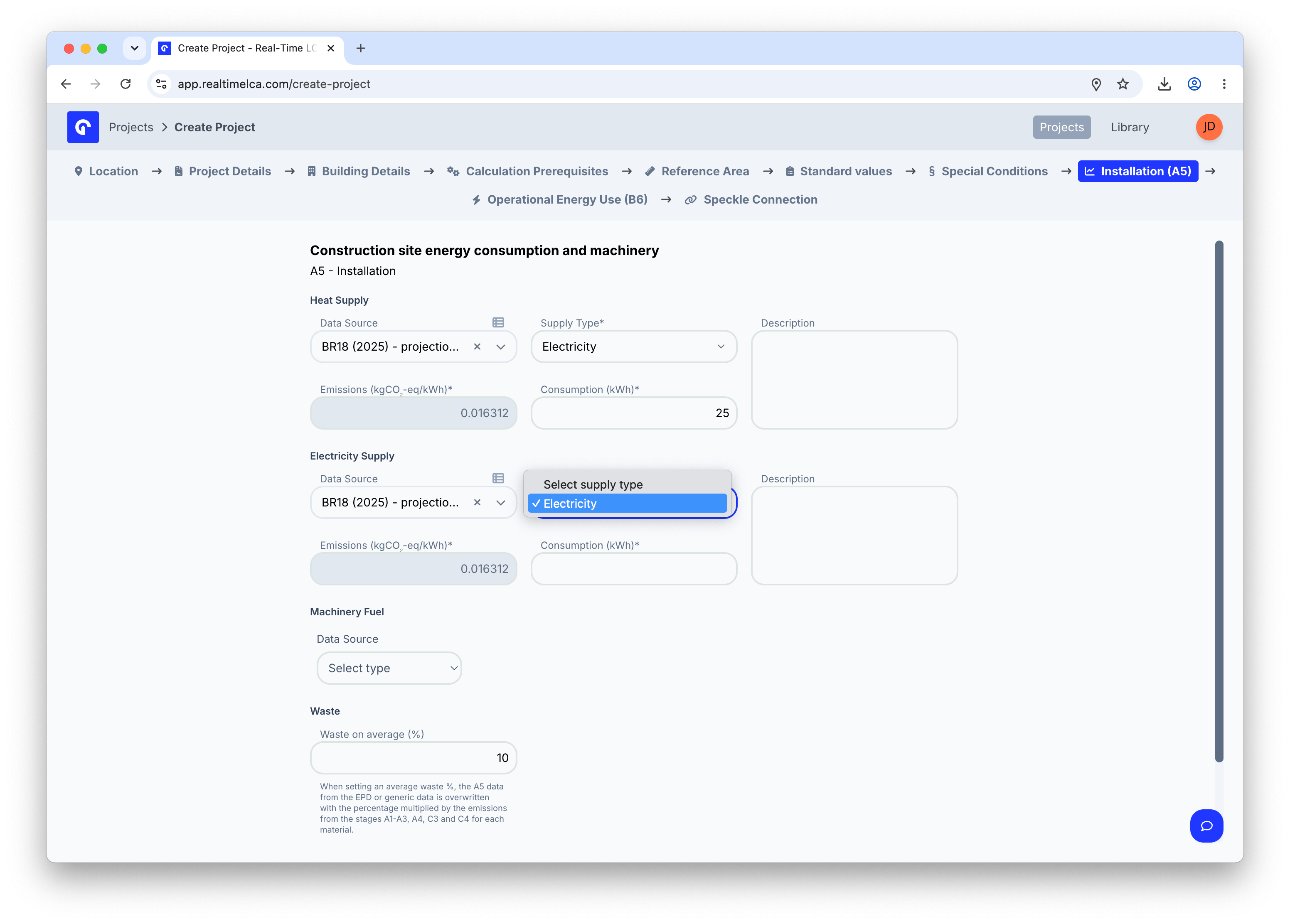
Electricity supply
Use the same Data Source / Supply Type / Consumption pattern for site electricity.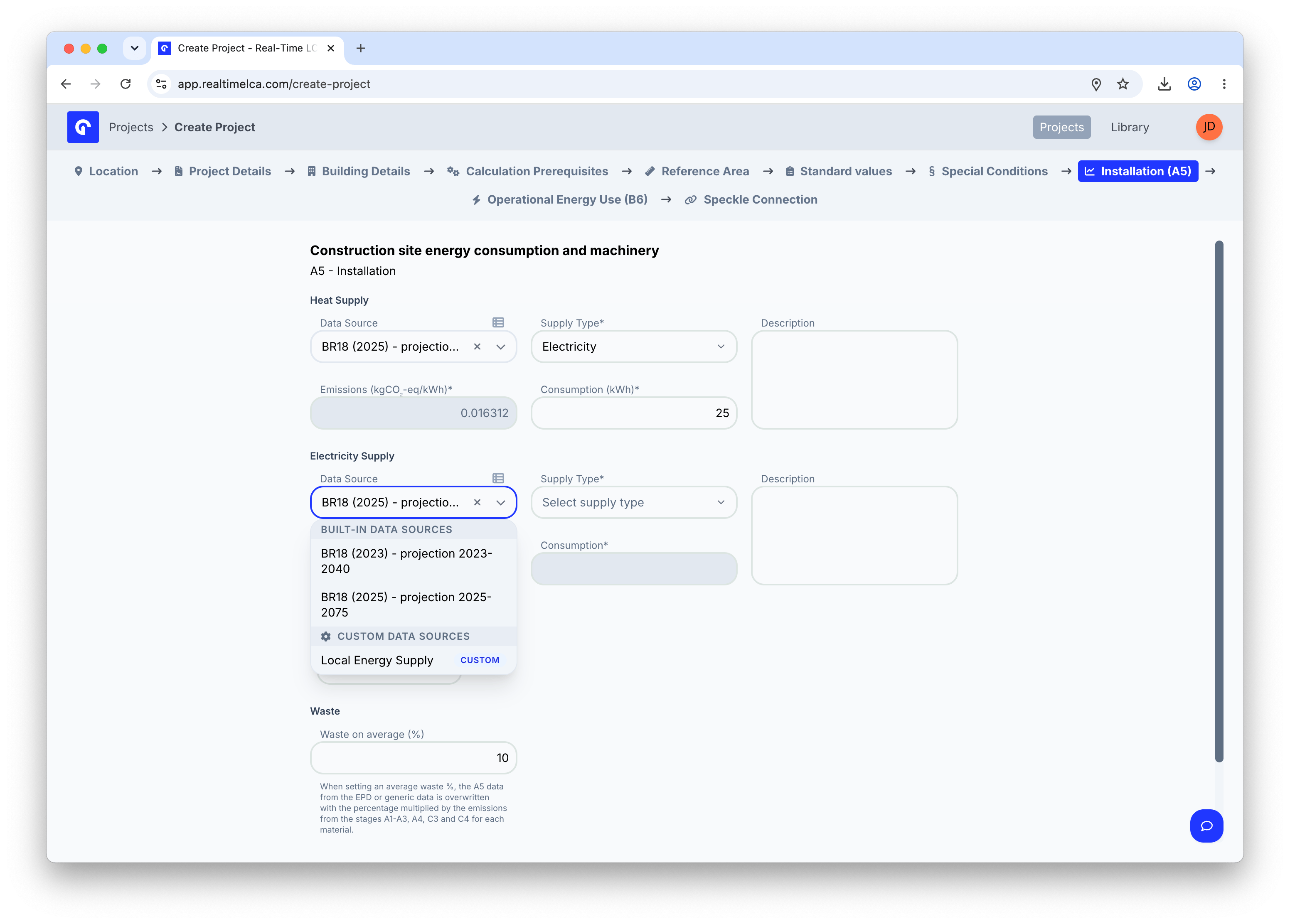
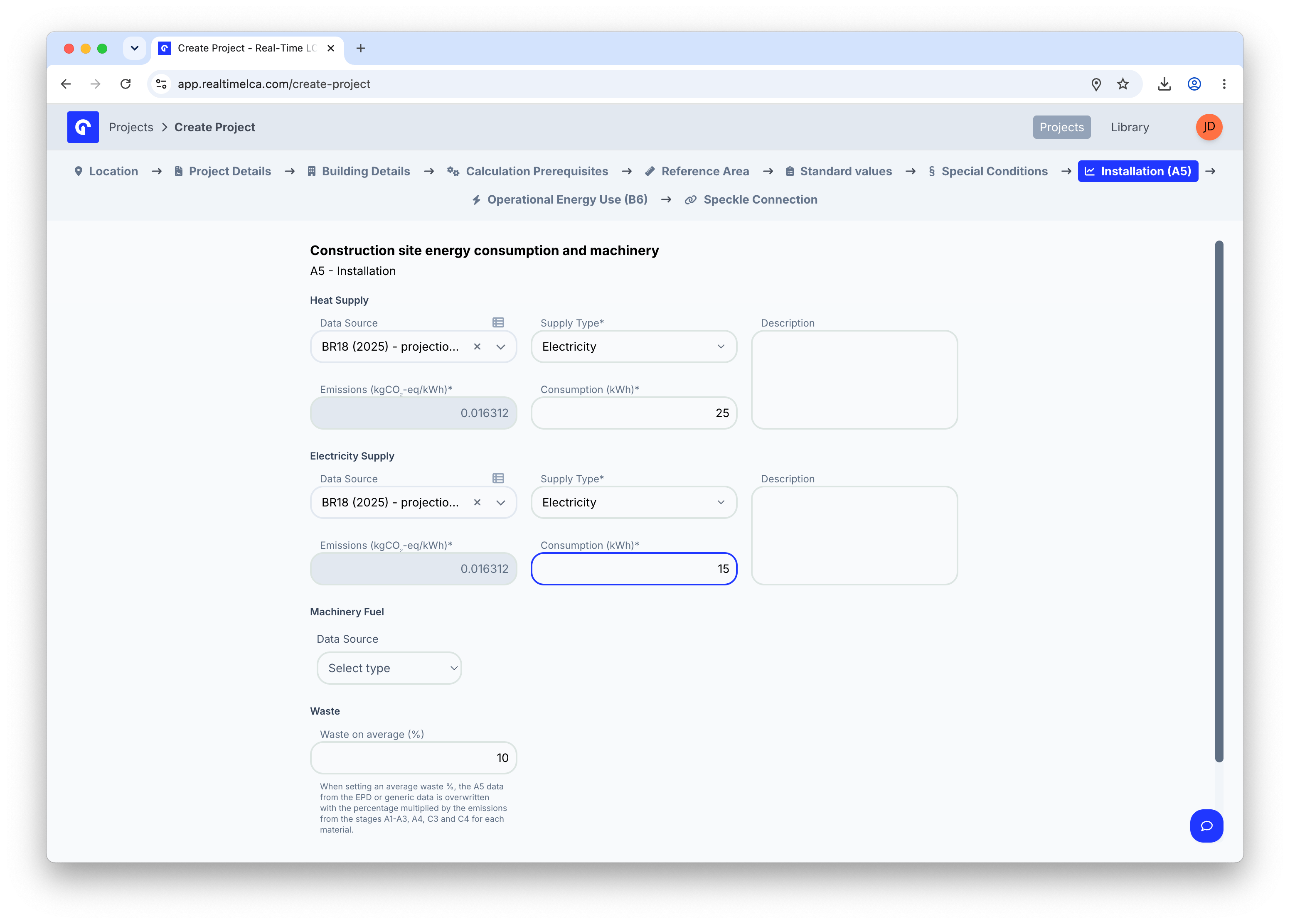
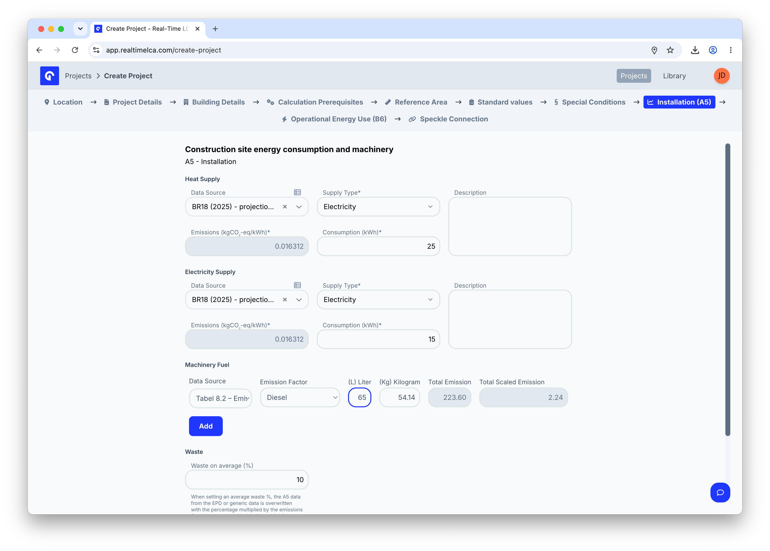
Machinery fuel
If the project tracks machinery fuel separately, pick a Data Source for the fuel emission factor.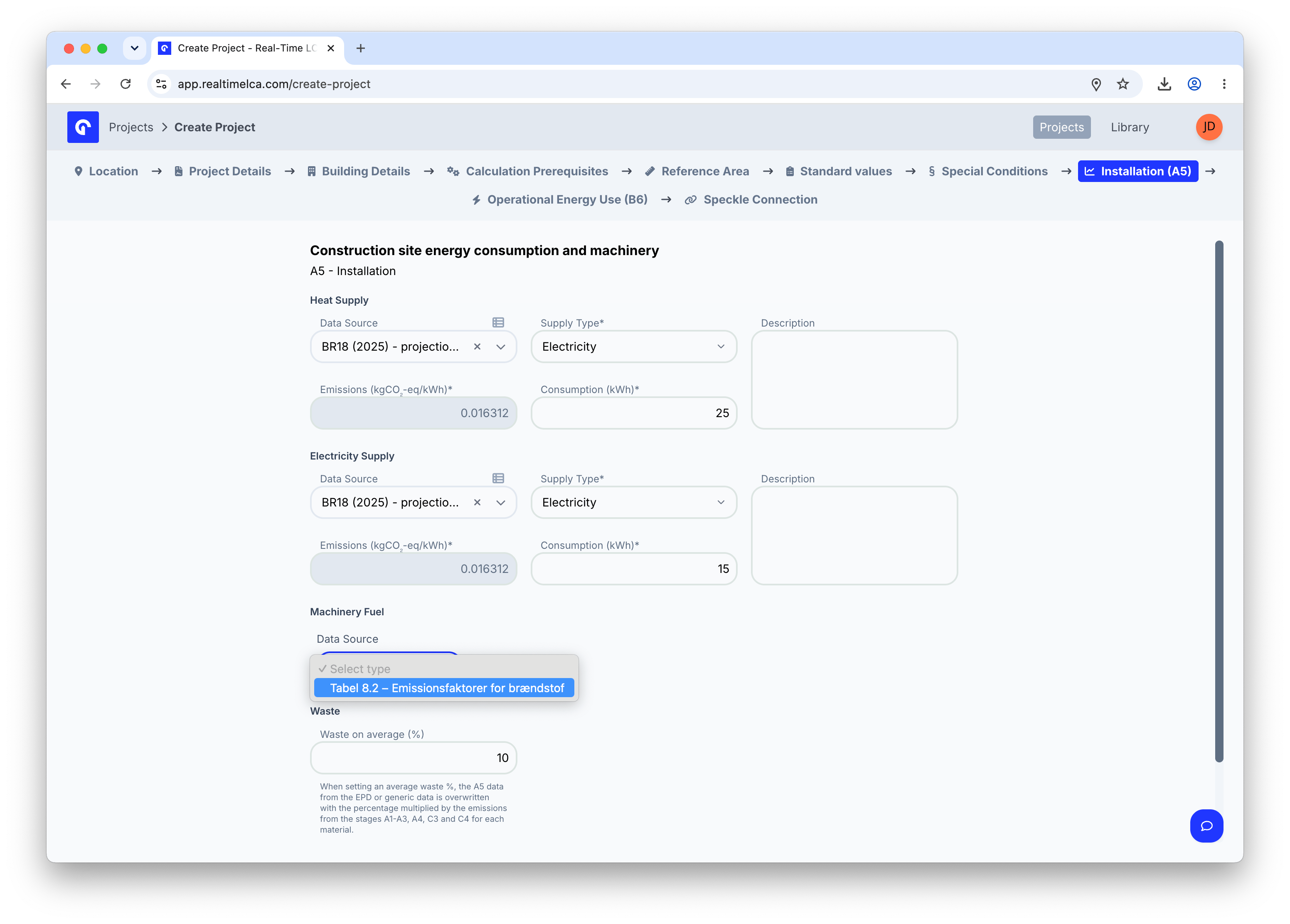
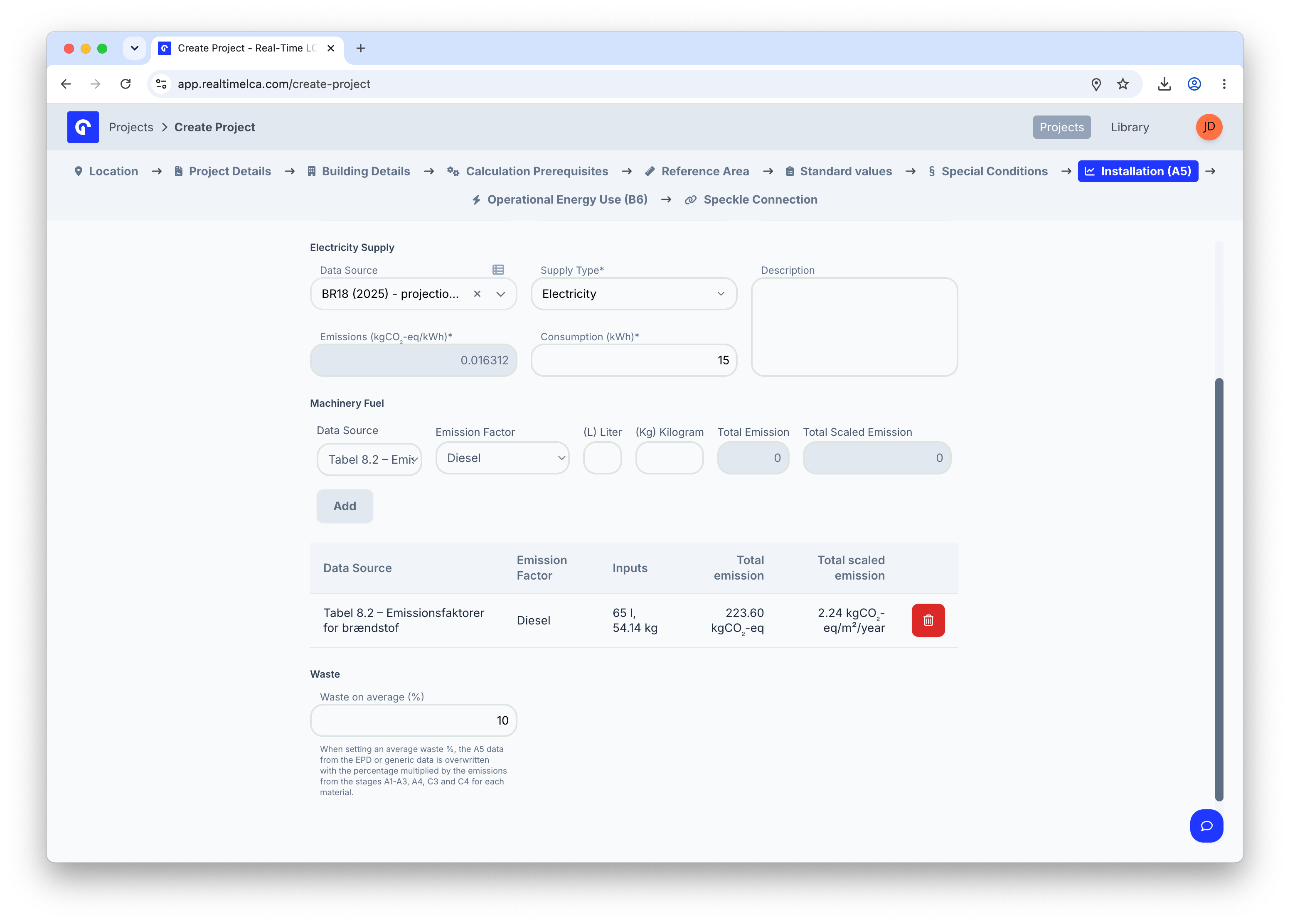
Waste on average (%)
The trailing Waste on average (%) field captures the project’s average construction waste. When set, the A5 data from each material’s EPD (or the generic fallback) is overwritten by this percentage multiplied by the emissions from A1–A3, A4, C3, and C4 for that material.Step 10: Enter operational energy use (B6)
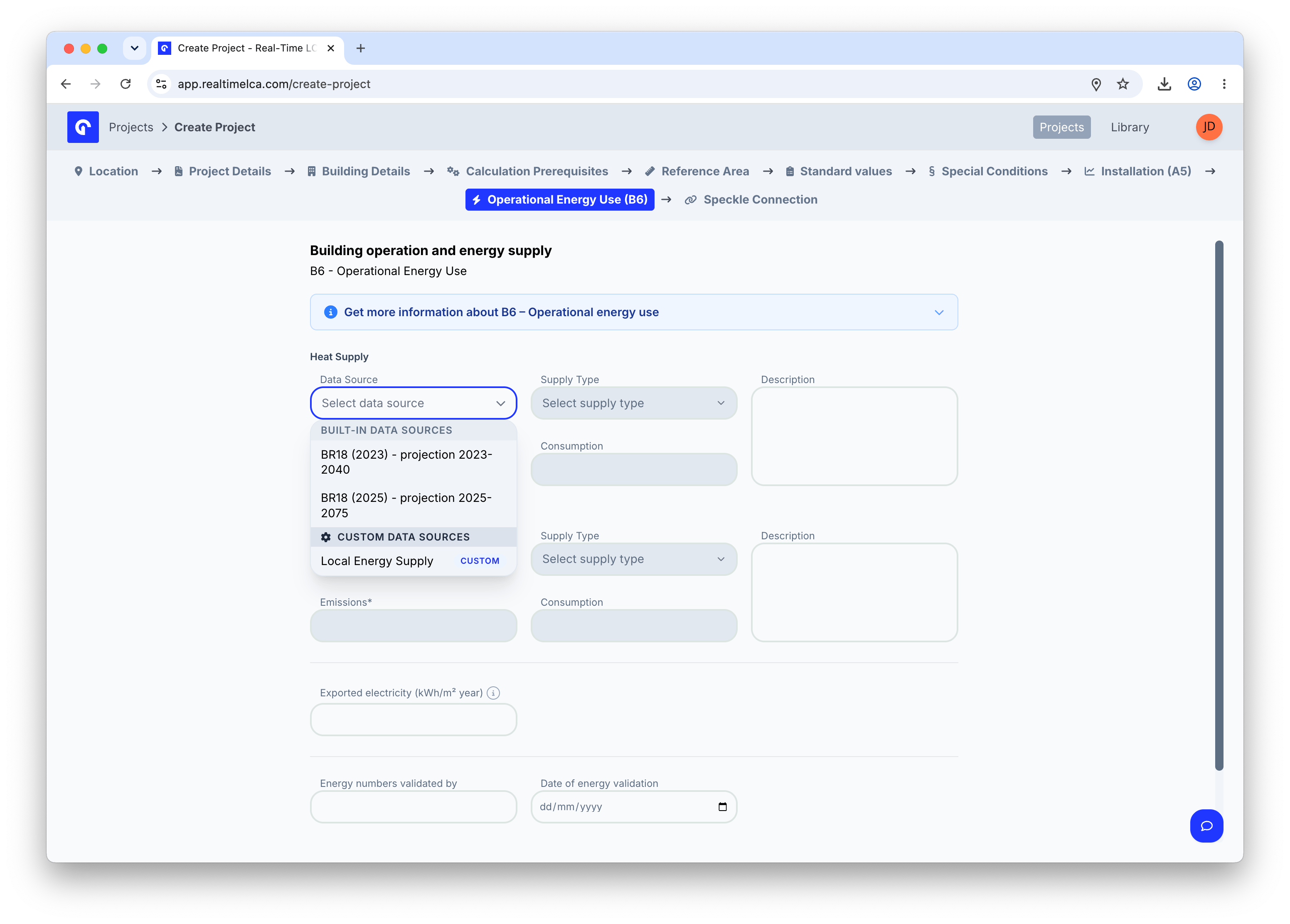
The Operational Energy Use (B6) tab is where you record the building’s expected operational heat and electricity demand. Real-Time LCA uses these to calculate B6 over the consideration period.Whether B6 is required, which supply types are available, and which data sources apply depend on the selected country and calculation type. See Methodology & Compliance for the rules behind B6.
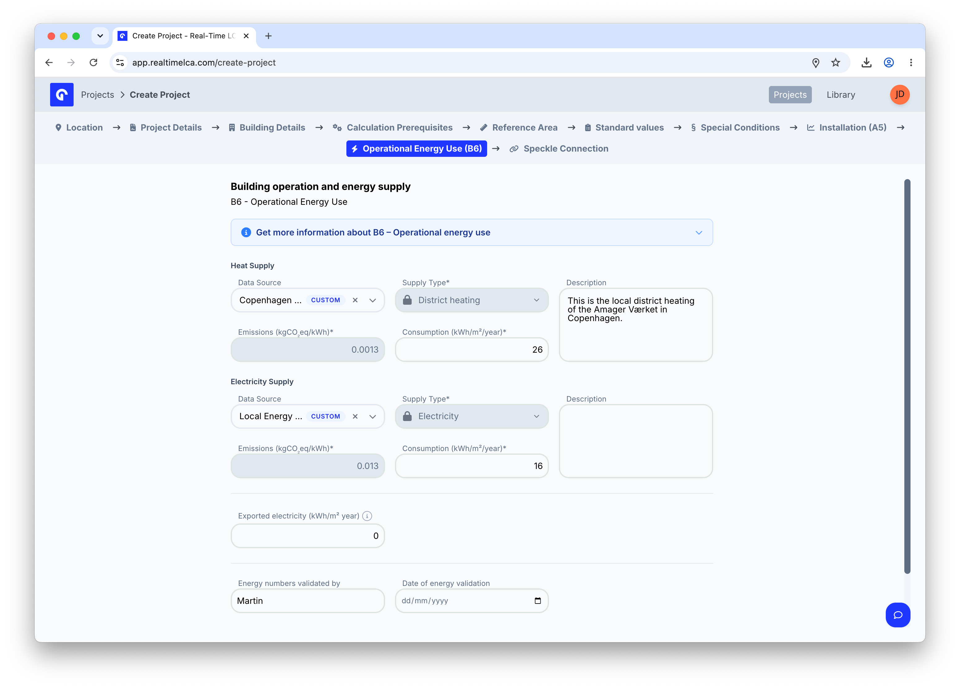
- Exported electricity (kWh/m²/year) — annual electricity exported back to the grid, subtracted from the B6 total.
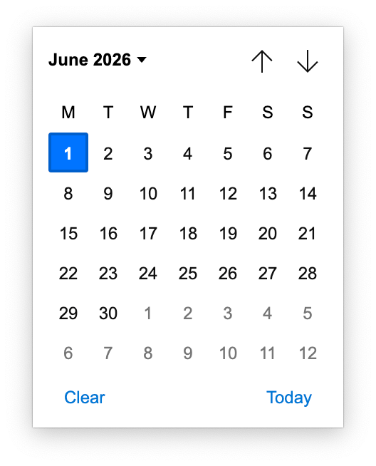
- Energy numbers validated by + Date of energy validation — record who signed off on the input numbers and when.
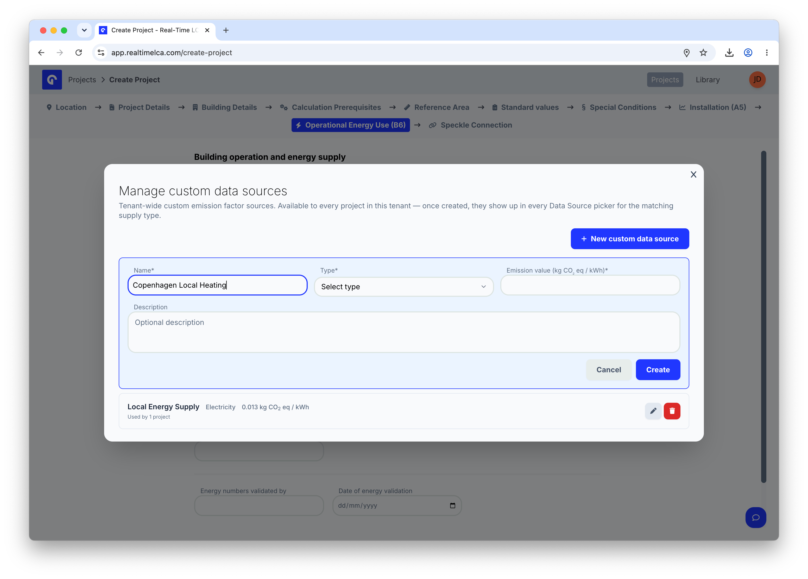
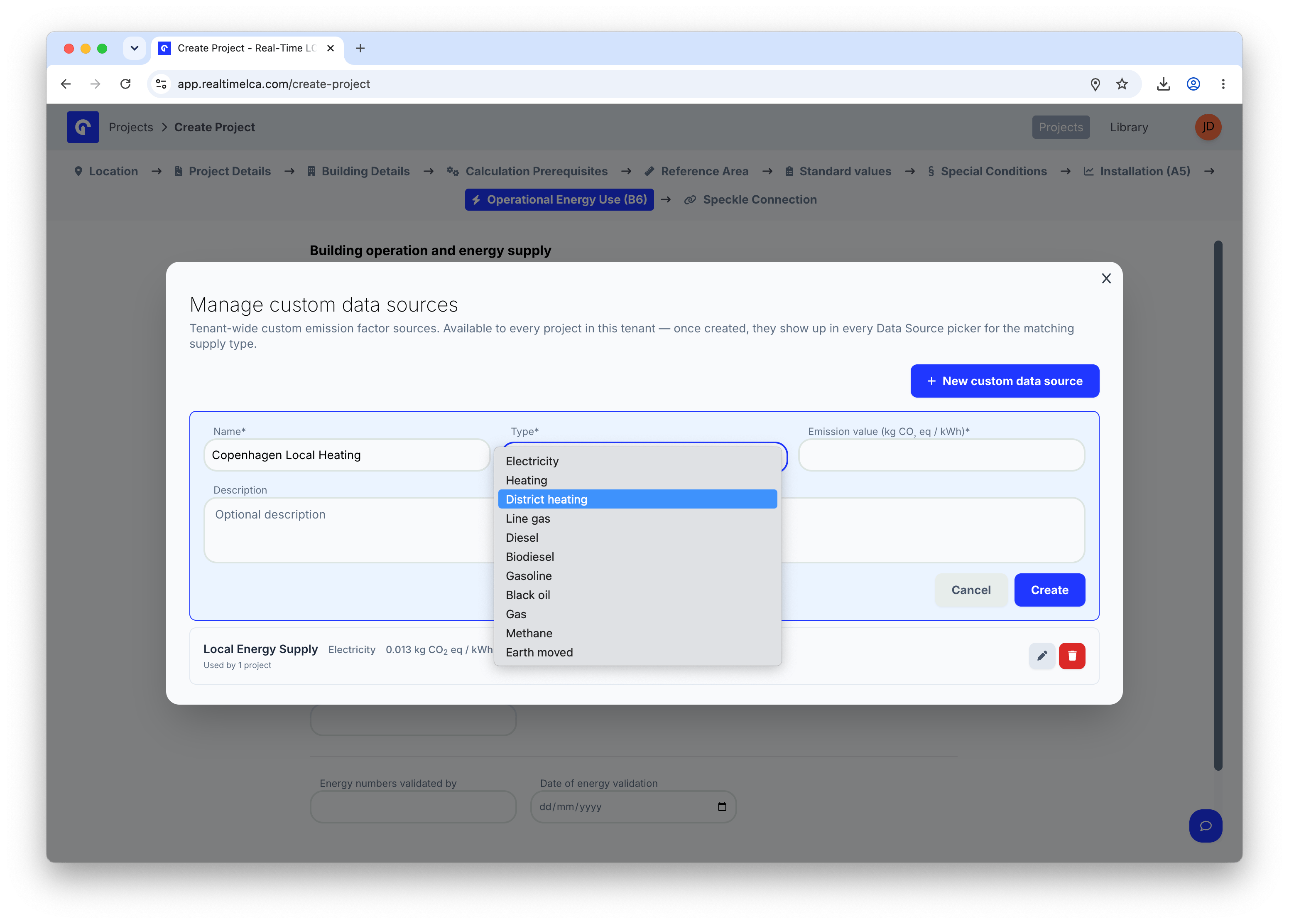
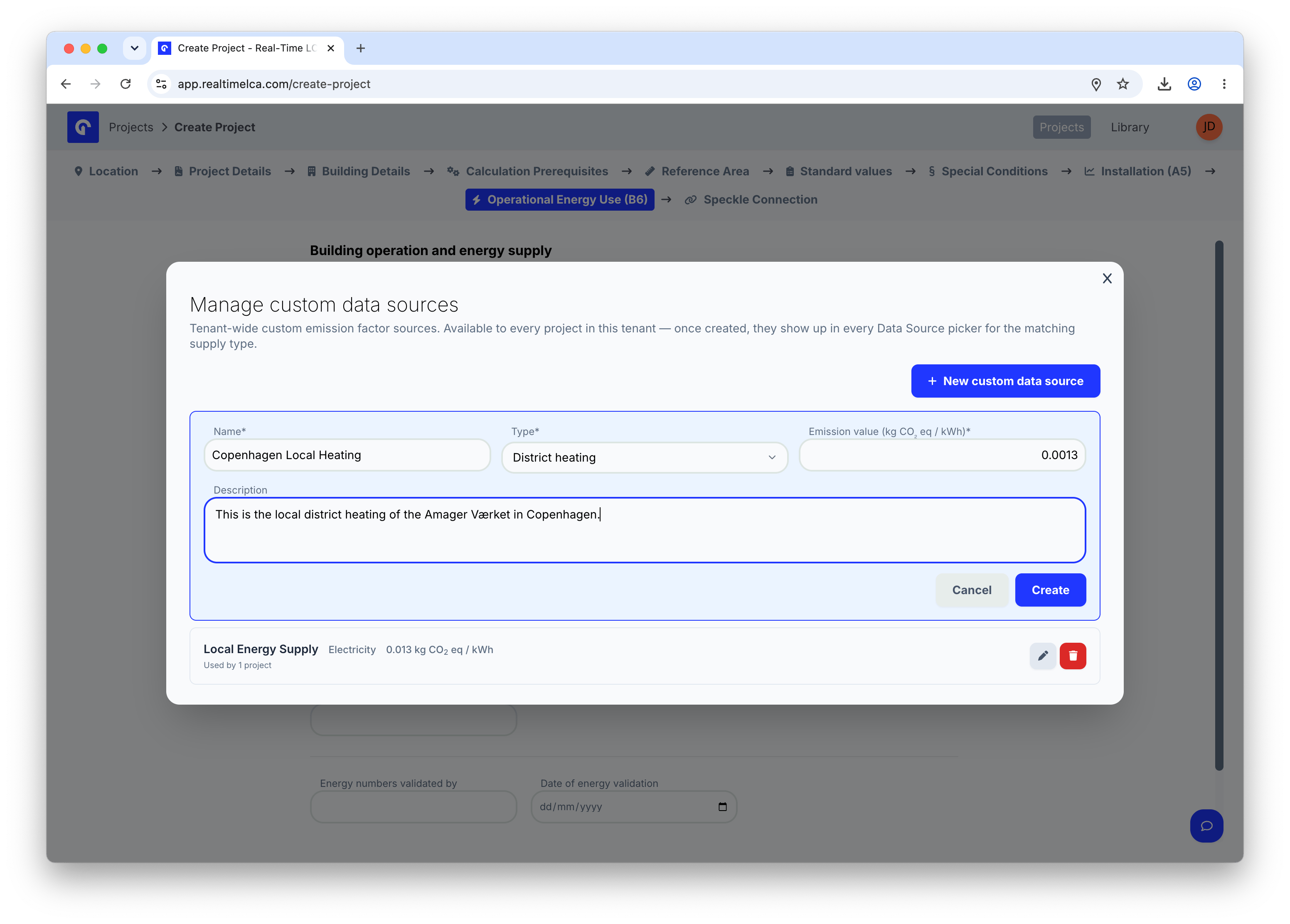
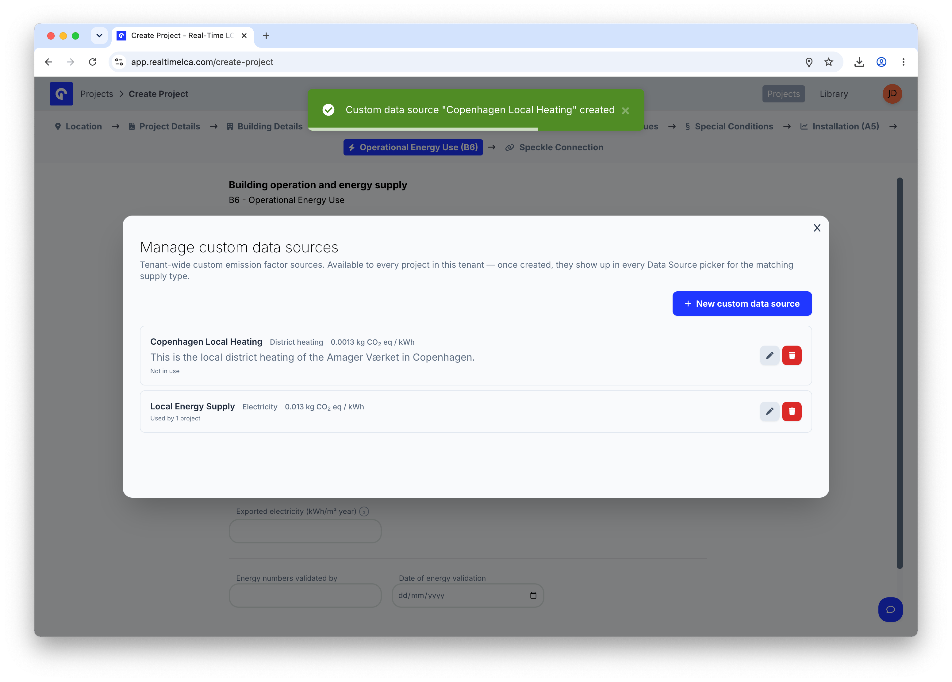
Using custom data sources
Both the A5 and B6 Data Source dropdowns are grouped into two sections: Built-in data sources (the regulation’s own projections) and Custom data sources (factors your tenant has created). Custom factors are useful when you have a verified local emission factor — for example, the district heating utility in your project’s region — that the regulation’s default does not reflect.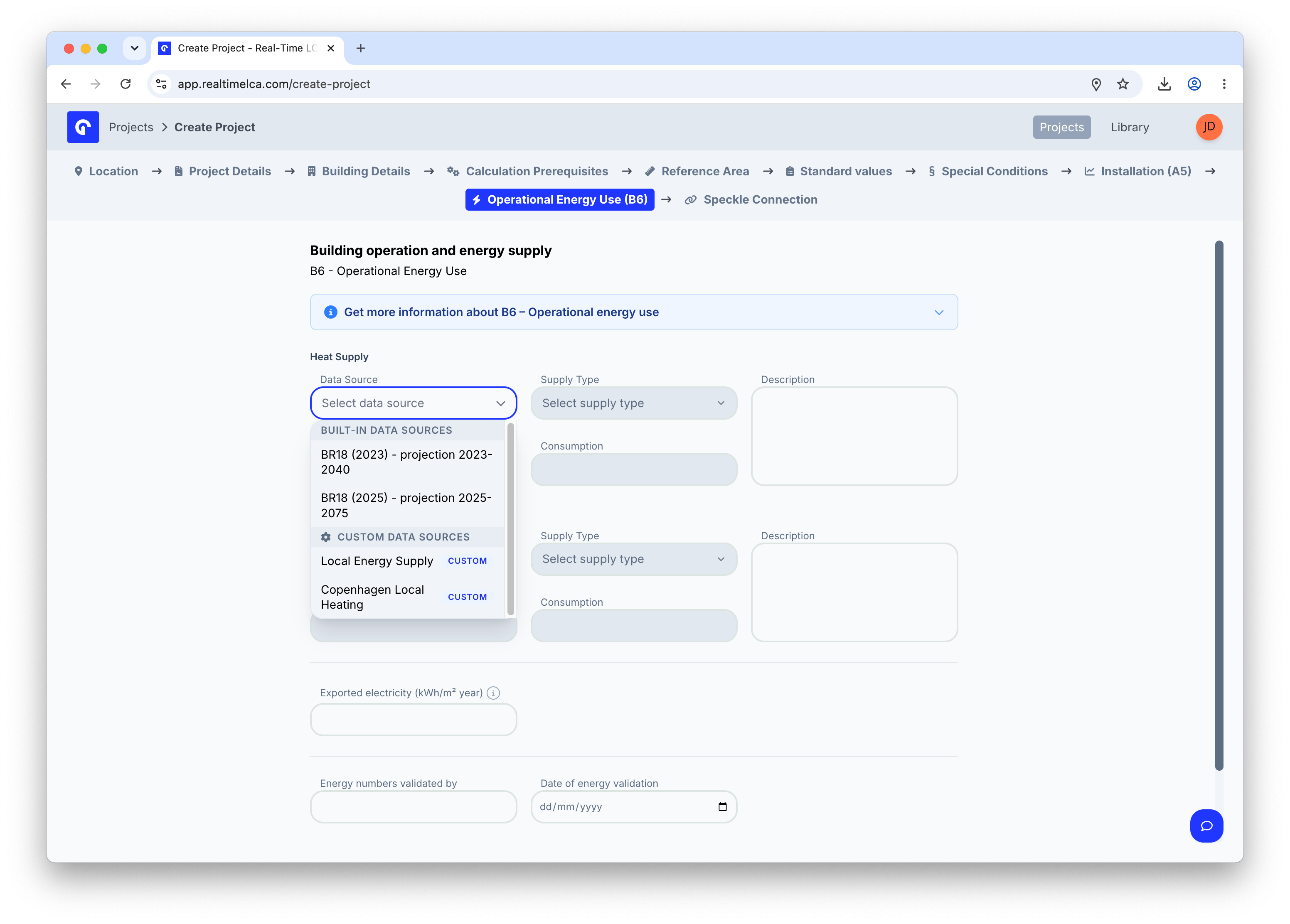
Step 11: Choose a Speckle connection
The last step decides how 3D model data flows into the project.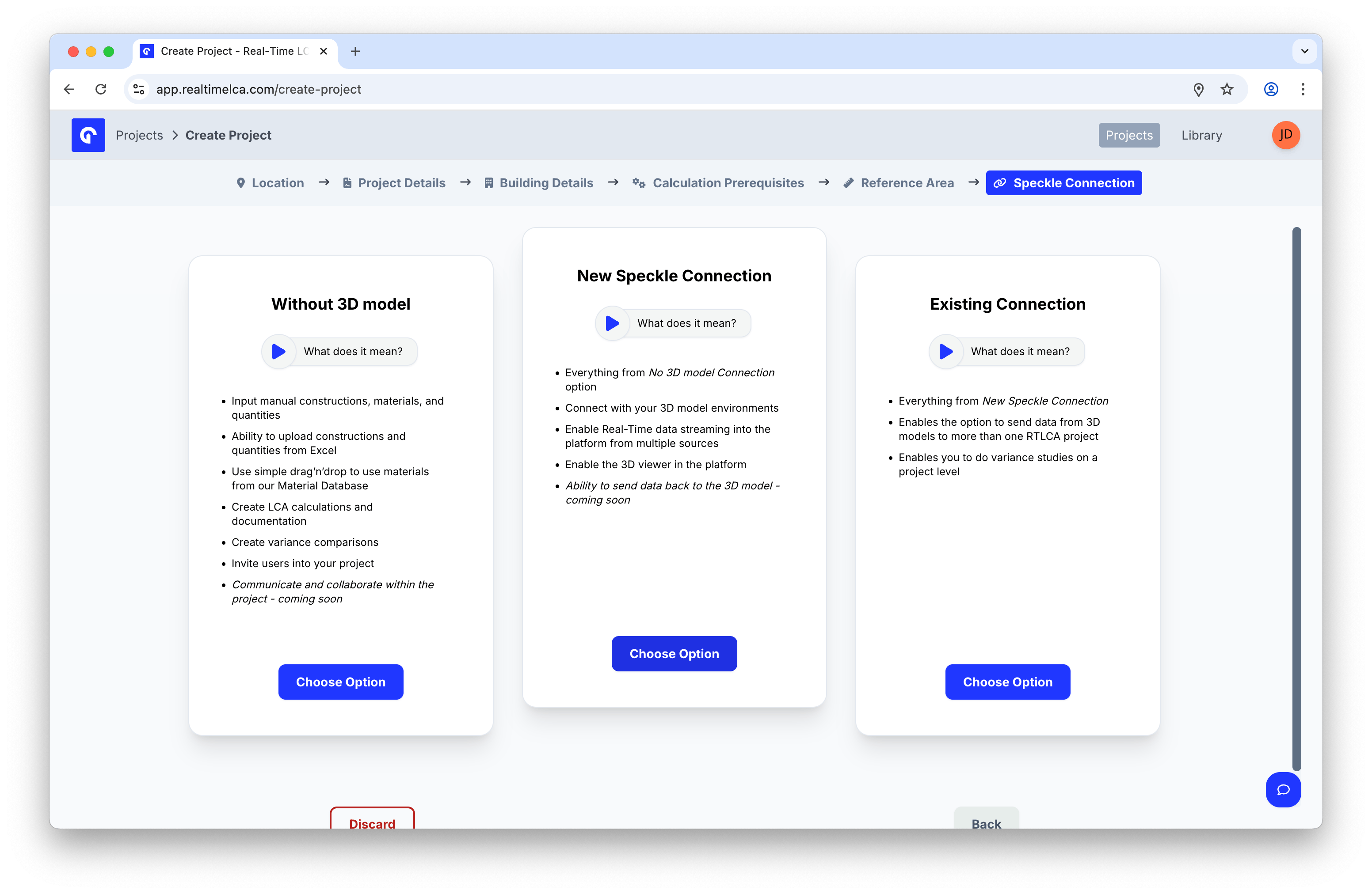
Without 3D model
Without 3D model
Best for early-phase or non-modeled projects.
- Input manual constructions, materials, and quantities.
- Upload constructions and quantities from Excel.
- Drag and drop materials from the material database.
- Create LCA calculations and documentation.
- Create variance comparisons.
- Invite users into your project.
New Speckle Connection
New Speckle Connection
Connect this project to a fresh Speckle stream.
- Everything from Without 3D model.
- Connect with your 3D modeling environments.
- Enable Real-Time data streaming into the platform from multiple sources.
- Enable the 3D viewer in the platform.
- Send data back to the 3D model (coming soon).
Existing Connection
Existing Connection
Reuse a Speckle connection that is already used by another project.
- Everything from New Speckle Connection.
- Send data from 3D models to more than one Real-Time LCA project.
- Run variance studies across projects.
Configure the Speckle models
If you chose New Speckle Connection or Existing Connection, configure which Speckle models the project should listen to.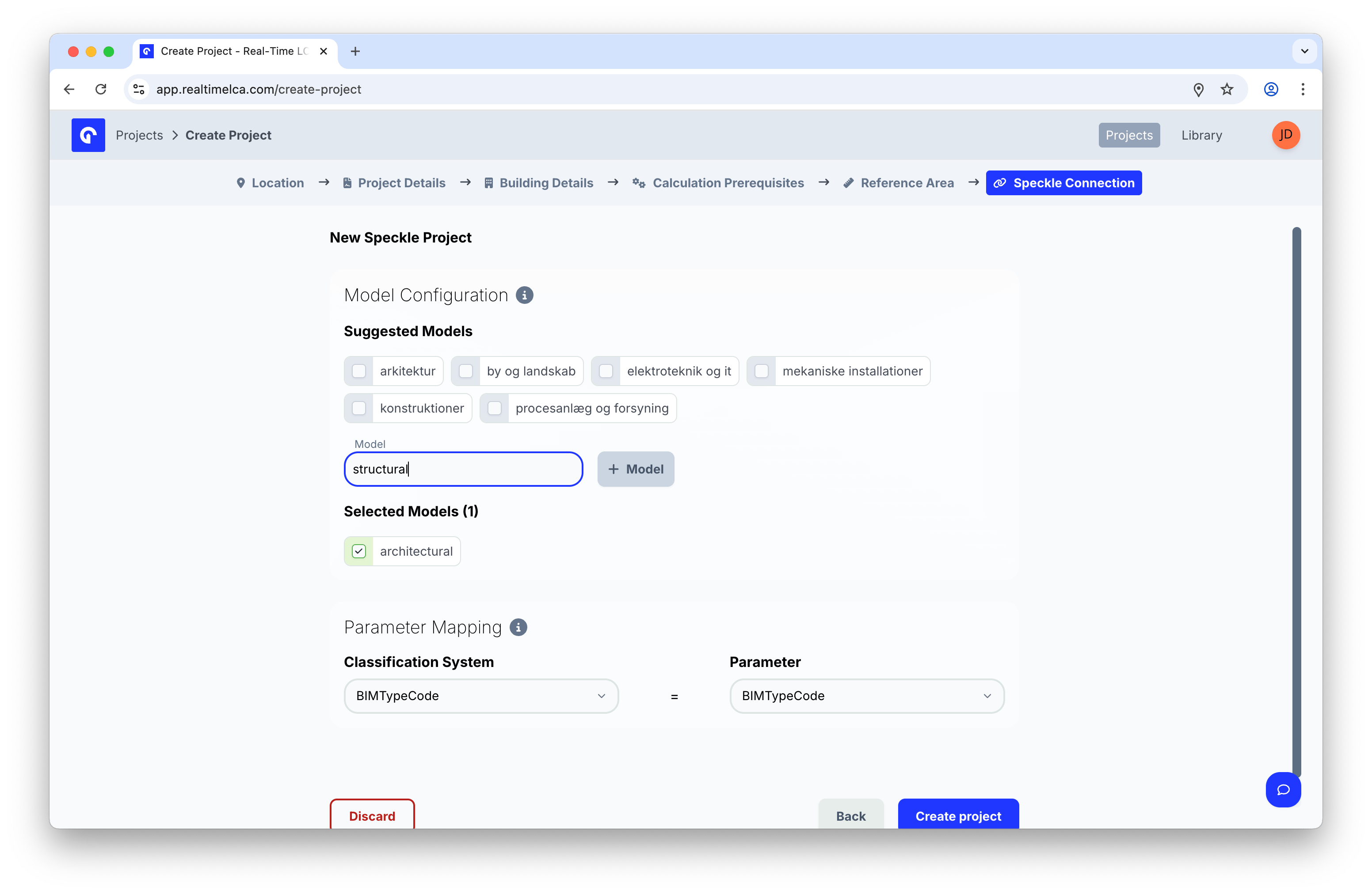
- Under Suggested Models, tick any of the common discipline models that apply (for example, arkitektur, konstruktioner, mekaniske installationer).
- To add a model that is not in the suggestions, type its name in Model and click + Model.
- Review the list under Selected Models and untick anything you do not need.
- Under Parameter Mapping, choose which Classification System in your model maps to the Real-Time LCA Parameter. The default mapping is
BIMTypeCode = BIMTypeCode.
Step 12: Create the project
When all steps are complete, click Create project. Real-Time LCA processes the configuration — this can take a moment.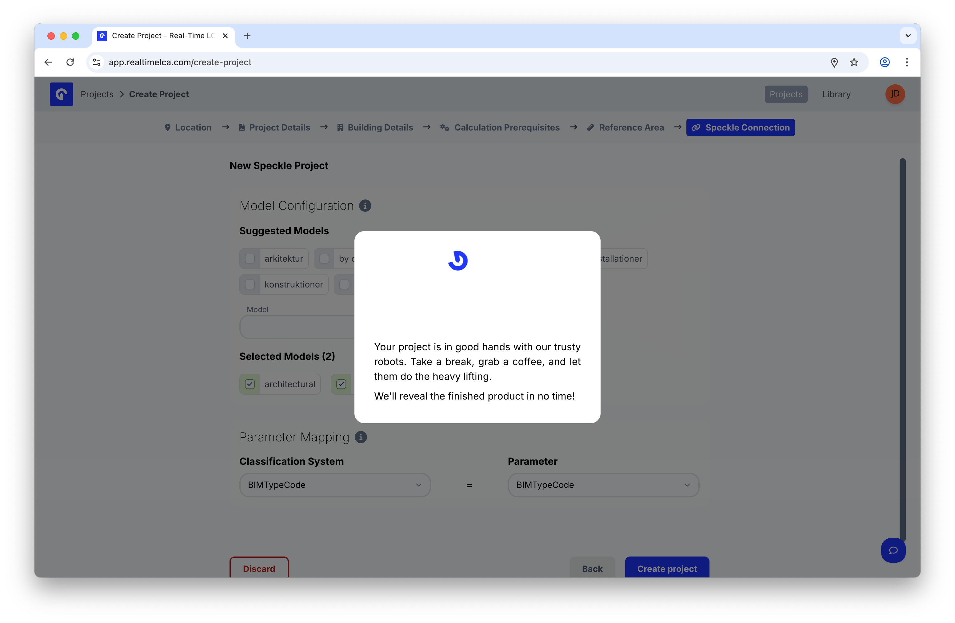
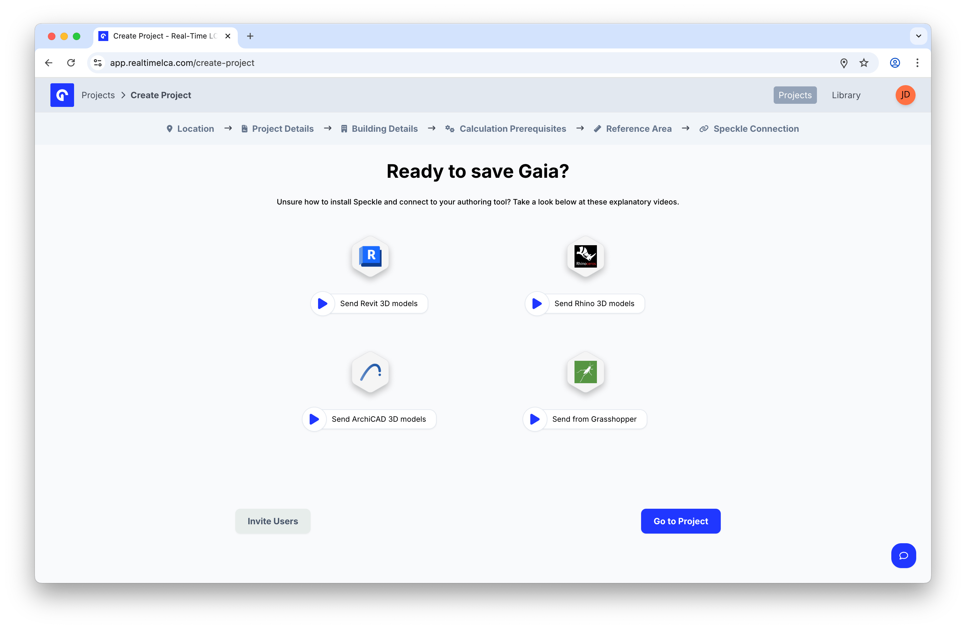
- Watch a short video on how to send 3D models from Revit, Rhino, ArchiCAD, or Grasshopper.
- Click Invite Users to add collaborators.
- Click Go to Project to open the project dashboard.